
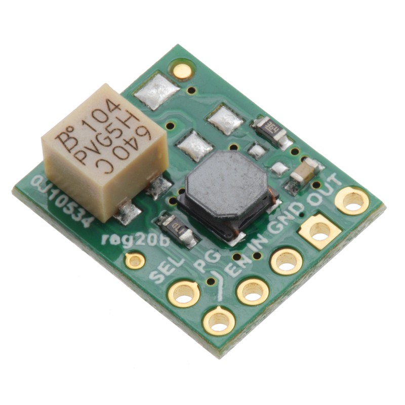
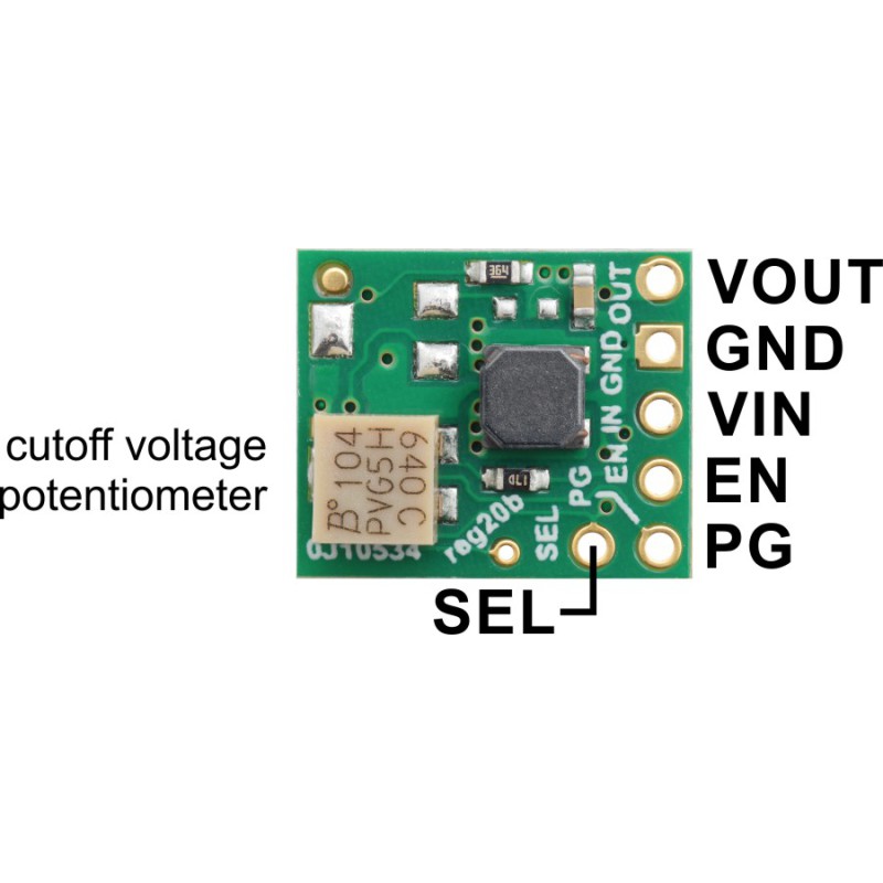
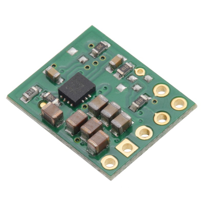
The S9V11x family of efficient switching regulators (also called switched-mode power supplies (SMPS) or DC-to-DC converters) use a buck-boost topology to convert both higher and lower input voltages to regulated output voltage. They take input voltages from 2 V to 16 V and increase or decrease them as necessary, offering typical efficiencies of 85% to 95% and typical continuous output currents over 1.5 A for input voltages close to or greater than the output voltage. (Note: The minimum start-up voltage is 3 V, but the regulator will operate down to 2 V after startup.)
The flexibility in input voltage offered by this family of regulators is especially well-suited for battery-powered applications in which the battery voltage begins above the regulated voltage and drops below as the battery discharges. Without the typical restriction on the battery voltage staying above the required voltage throughout its life, new battery packs and form factors can be considered.
These regulators have short-circuit protection, and thermal shutdown prevents damage from overheating. The boards do not have built-in protection against reverse voltage, but reverse-voltage protection modules are available for adding that functionality. Note that the startup current is limited to approximately 700 mA until the output voltage reaches the nominal voltage; after startup, the available current is a function of the input voltage (see the maximum continuous output current graph below).
The different members of this family offer different output voltage options, from fixed voltages (some with selectable alternatives) to adjustable voltages that can be set anywhere between 2.5 V and 9 V. Some versions also have an adjustable low-voltage cutoff that can be set anywhere in the 2 V to 16 V output voltage range and used to prevent your battery from over-discharging.
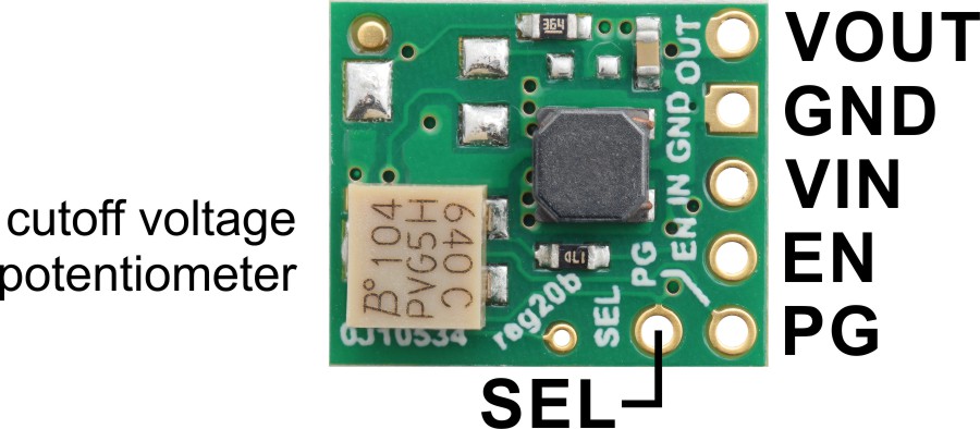
Features
- Input voltage: 2 V to 16 V (note: this regulator requires 3 V to start, but it can operate down to 2 V after startup)
- Fixed 5 V output with +5/-3% accuracy (can be changed to 6 V using the SEL pin)
- Max continuous output current when input voltage ≥ output voltage: 1.5 A (note: startup current is limited to 700 mA until output voltage reaches the nominal voltage; see the maximum continuous output current graph below for current capabilities across the full input voltage range)
- Precision-adjustable low-voltage cutoff with hysteresis can be used to protect batteries from over-discharging
- Enable input can be used to put the board into a low-power state where it typically draws 7 µA per volt on VIN
- Low quiescent current: < 0.2 mA for most of the operating range (see the quiescent current graph below)
- Power-good output can be used for sequencing, fault detection, and voltage monitoring
- Integrated over-temperature and short-circuit protection
- Power-saving feature maintains high efficiency at low currents
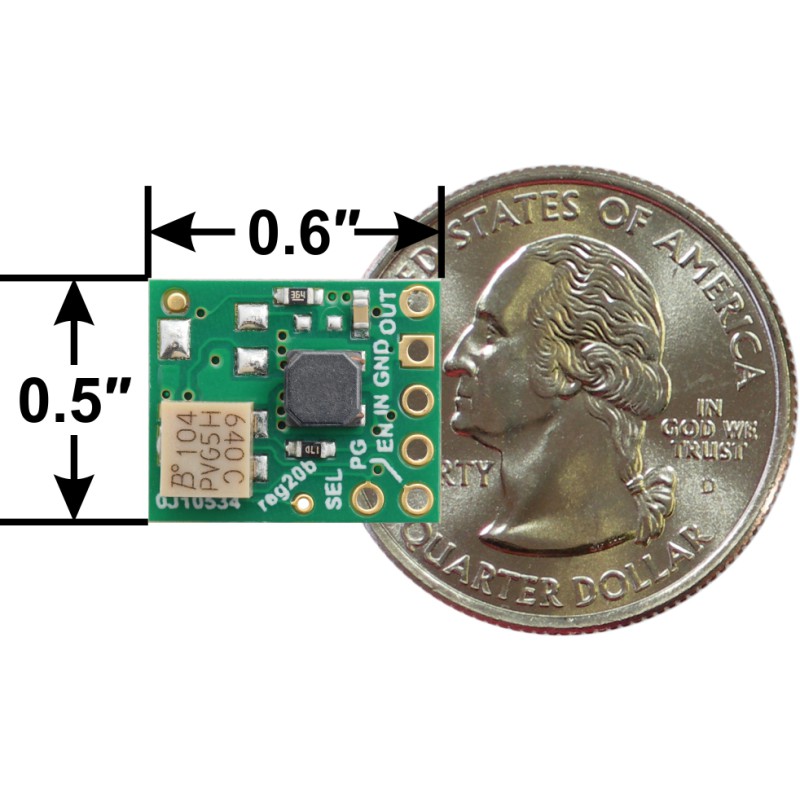
- Compact size: 0.5″ × 0.6″ × 0.25″ (12.7 × 15.3 × 6.4 mm)
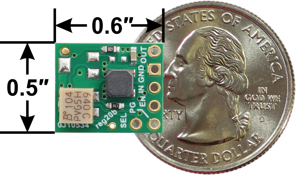
Dimensions
| Size: | 0.5″ × 0.6″ × 0.25″1 |
|---|---|
| Weight: | 0.8 g1 |
General specifications
| Minimum operating voltage: | 2 V2 |
|---|---|
| Maximum operating voltage: | 16 V |
| Continuous output current: | 1.7 A3 |
| Output voltage: | 5 V4 |
| Reverse voltage protection?: | N |
| Maximum quiescent current: | 0.4 mA5 |
| Low-voltage cutoff: | precision adjustable |
| Output type: | fixed 5V (default), 6V selectable |