
Overview
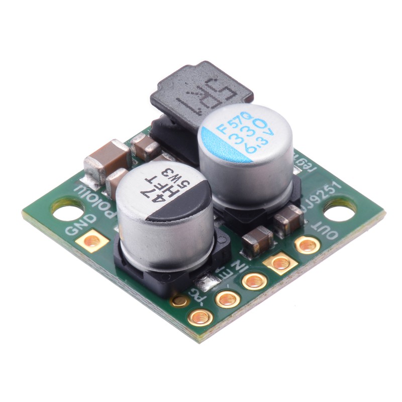
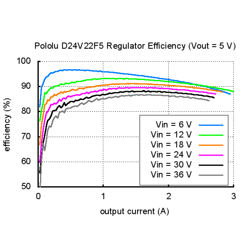
The D24V22Fx family of step-down voltage regulators generates lower output voltages from input voltages as high as 36 V. They are synchronous switching regulators (also called switched-mode power supplies (SMPS) or DC-to-DC converters) with typical efficiencies of 85% to 95%, which is much more efficient than linear voltage regulators, especially when the difference between the input and output voltage is large. These regulators can typically support continuous output currents between 1.4 A and 2.6 A, though the actual available output current is a function of the input voltage and efficiency (see the Typical efficiency and Maximum continuous output current sections below). In general, the available output current is a little higher for the lower-voltage versions than it is for the higher-voltage versions, and it decreases as the input voltage increases.
These regulators have a typical quiescent (no load) current draw of around 1 mA, and an enable pin can be used to put the boards in a low-power state that reduces the quiescent current to approximately 5 µA to 10 µA per volt on VIN.
The modules have built-in reverse-voltage protection, short-circuit protection, a thermal shutdown feature that helps prevent damage from overheating, and a soft-start feature that reduces inrush current.
Several different fixed output voltages are available:
- D24V22F3: Fixed 3.3V output
- D24V22F5: Fixed 5V output
- D24V22F6: Fixed 6V output
- D24V22F7: Fixed 7.5V output
- D24V22F9: Fixed 9V output
- D24V22F12: Fixed 12V output
The different voltage versions of this regulator all look very similar, so you should consider adding your own distinguishing marks or labels if you will be working simultaneously with multiple versions. This product page applies to all versions of the D24V22Fx family.
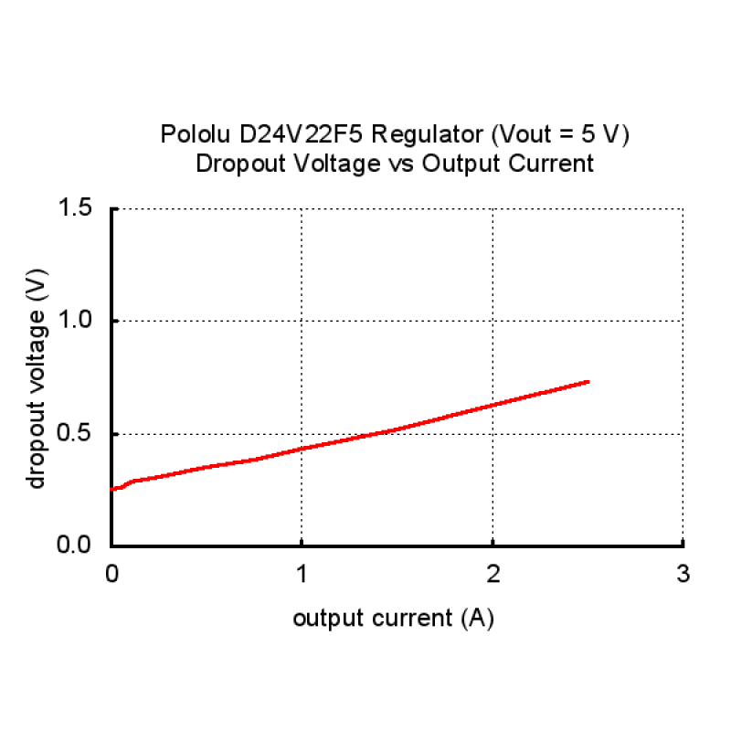
The D24V22Fx family is intended to replace our older D24V25Fx family of step-down voltage regulators. The two designs have the same size and similar current capabilities and input voltage ranges, but they do not have the same pinout and are based on different internal circuits, so there are fundamental differences in operation. In particular, these newer D24V22Fx regulators have much lower dropout voltages and provide a “power good” signal, and the newer design allows for higher output voltages (e.g. 12 V).
For higher-power alternatives, please consider our D36V28Fx family of step down regulators that can handle current between 2 A and 4 A and take input voltages up to 50 V.
We manufacture these boards in-house at our Las Vegas facility, which gives us the flexibility to make these regulators with customized components to better meet the needs of your project. For example, if you have an application where the input voltage will always be below 20 V and efficiency is very important, we can make these regulators a bit more efficient at high loads by replacing the 40V reverse voltage protection MOSFET with a 20V one. We can also customize the output voltage. If you are interested in customization, please contact us.
Features
- Input voltage:
- 4 V to 36 V for the version that outputs 3.3 V
- [output voltage + dropout voltage] to 36 V for output voltages of 5 V and higher (see the dropout voltage section for details)
- Fixed 3.3 V, 5 V, 6 V, 7.5 V, 9 V, or 12 V output (depending on regulator version) with 4% accuracy
- Typical maximum continuous output currents between 1.4 A and 2.6 A (see the maximum continuous output current graph below)
- Typical efficiency of 85% to 95%, depending on input voltage, output voltage, and load (see the efficiency graph below)
- Switching frequency: ~400 kHz
- Integrated reverse-voltage protection, over-current and short-circuit protection, over-temperature shutoff, and soft-start
- 1 mA typical no-load quiescent current; this can be reduced to approximately 5 µA to 10 µA per volt on VIN by disabling the board (see the quiescent current graph below)
- Power-good indicator can be used to tell when the regulator has reached and is maintaining its target output voltage
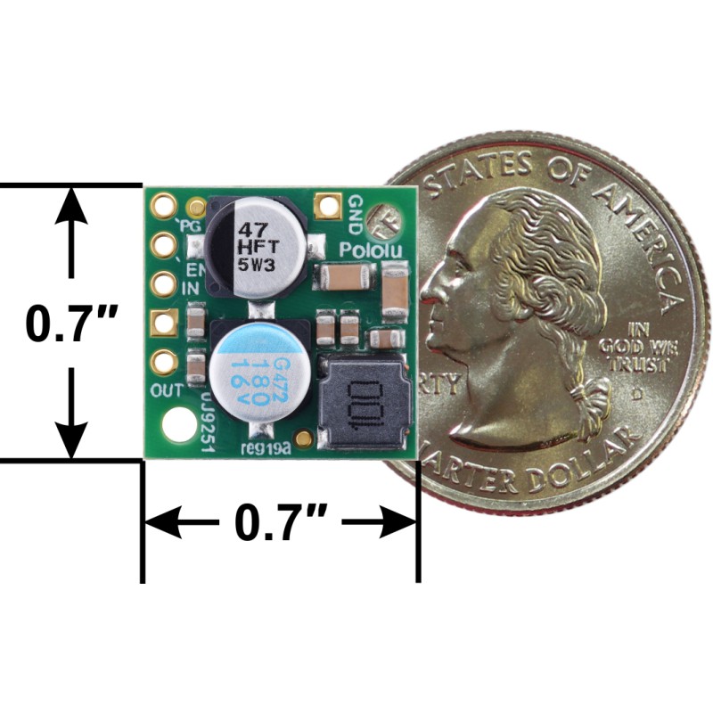
- Compact size: 0.7″ × 0.7″ × 0.31″ (17.8 mm × 17.8 mm × 8 mm)
- Two 0.086″ mounting holes for #2 or M2 screws
Using the regulator
Connections
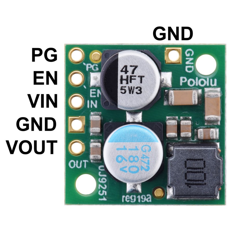
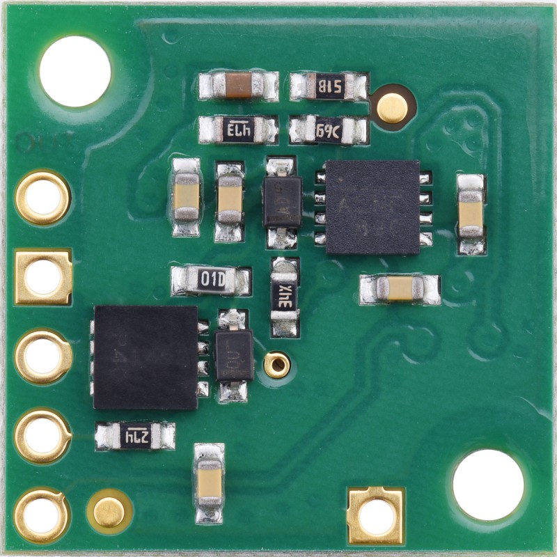
These buck regulators have five main connection points for five different electrical nodes: power good (PG), enable (EN), input voltage (VIN), ground (GND), and output voltage (VOUT). The board also features a second ground connection point off the main row of connections that might be convenient for applications where you are soldering wires directly to the board rather than using it in a breadboard
Dimensions
| Size: | 0.7″ × 0.7″ × 0.31″1 |
|---|---|
| Weight: | 2.3 g1 |
General specifications
| Minimum operating voltage: | 5.3 V2 |
|---|---|
| Maximum operating voltage: | 36 V |
| Continuous output current: | 2.2 A3 |
| Output voltage: | 5 V |
| Reverse voltage protection?: | Y |
| Maximum quiescent current: | 3 mA4 |
Identifying markings
| PCB dev codes: | reg19a |
|---|---|
| Other PCB markings: | 0J9251 |
Notes:
- 1
- Without included optional headers.
- 2
- For small loads; this voltage rises approximately linearly up to around 5.8 V at 2.5 A output.
- 3
- Typical max continuous output current at 24 V in. Actual achievable continuous output current is a function of input voltage and is limited by thermal dissipation. See the output current graph under the description tab for more information.
- 4
- Typical worst case; quiescent current is typically around 1 mA for most of the operating range. The ENABLE pin can be used to reduce the quiescent current to less than 10 μA per volt on VIN.