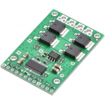
Pololu High-Power Motor Driver 24v23 CS
Pololu High-Power Motor Driver 24v23 CS
The Pololu high-power motor driver is a discrete MOSFET H-bridge designed to drive large DC brushed motors. The H-bridge is made up of one N-channel MOSFET per leg, and most of the board’s performance is determined by these MOSFETs (the rest of the board contains the circuitry to take user inputs and control the MOSFETs). The MOSFET datasheet is available under the “Resources” tab. The MOSFETs have an absolute maximum voltage rating of 40 V; higher voltages can permanently destroy the motor driver. Under normal operating conditions, ripple voltage on the supply line can raise the maximum voltage to more than the average or intended voltage, so a safe maximum voltage is approximately 34 V.

The versatility of this driver makes it suitable for a large range of currents and voltages: it can deliver up to 23 A of continuous current with a board size of only 1.8" by 1.2" and no required heat sink. With the addition of a heat sink, it can drive a motor with up to about 37 A of continuous current. The module offers a simple interface that requires as few as two I/O lines while allowing for both sign-magnitude and locked-antiphase operation, and an optional third control input unique to this board allows for coasting. This board also features a current-sensing circuit that measures bidirectional motor current with a magnitude up to 30 A and outputs an analog voltage.
Integrated detection of various short-circuit conditions protects against common causes of catastrophic failure; however, please note that the board does not include reverse power protection or any over-current or over-temperature protection. We recommend you use the integrated current sensor to keep the driver from delivering more current than it can safely handle.

Using the Motor Driver
Connections
The motor and motor power connections are on one side of the board, and the control connections (5V logic) are on the other side. The motor supply should be capable of delivering the high current the motor will require, and a large capacitor should be installed between V+ and ground close to the motor driver to decrease electrical noise. Two axial capacitors are included and one or both can be installed by soldering them into the V+ and GND pins (labeled '+' and '-' on the bottom silkscreen) along the long edges of the board. Such installations are compact but might limit heat sinking options; also, depending on the power supply quality and motor characteristics, a larger capacitor might be required. There are two options for connecting to the high-power signals (V+, OUTA, OUTB, GND): large holes on 0.2" centers, which are compatible with the included terminal blocks, and pairs of 0.1"-spaced holes that can be used with perfboards, breadboards, and 0.1" connectors.
Motor Control Options
The motor driver can be used in several different modes:
| Motor Driver Truth Table | |||||
|---|---|---|---|---|---|
| PWMH | PWML | DIR | OUTA | OUTB | Operation |
| H | H | L | GND | V+ | Forward |
| H | H | H | V+ | GND | Backward |
| L | H | X | GND | GND | Brake Low |
| H | L | X | V+ | V+ | Brake High |
| L | L | X | Z | Z | Coast |
Dimensions
| Size: | 1.8" x 1.2" |
|---|---|
| Weight: | 7 g1 |
General specifications
| Motor channels: | 1 |
|---|---|
| Minimum operating voltage: | 5.5 V |
| Maximum operating voltage: | 40 V |
| Continuous output current per channel: | 23 A2 |
| Current sense: | 0.066 V/A3 |
| Maximum PWM frequency: | 40 kHz4 |
| Maximum logic voltage: | 5.5 V |
| MOSFET on-resistance (max per leg): | 3.6 mΩ |
| Reverse voltage protection?: | N |
ביקורת : הערה ללא תרגום מ HTML!
דירוג רע טוב
הכנס את הקוד התיבה


