


12V, 2.4A Step-Down Voltage Regulator D36V28F12
12V, 2.4A Step-Down Voltage Regulator D36V28F12
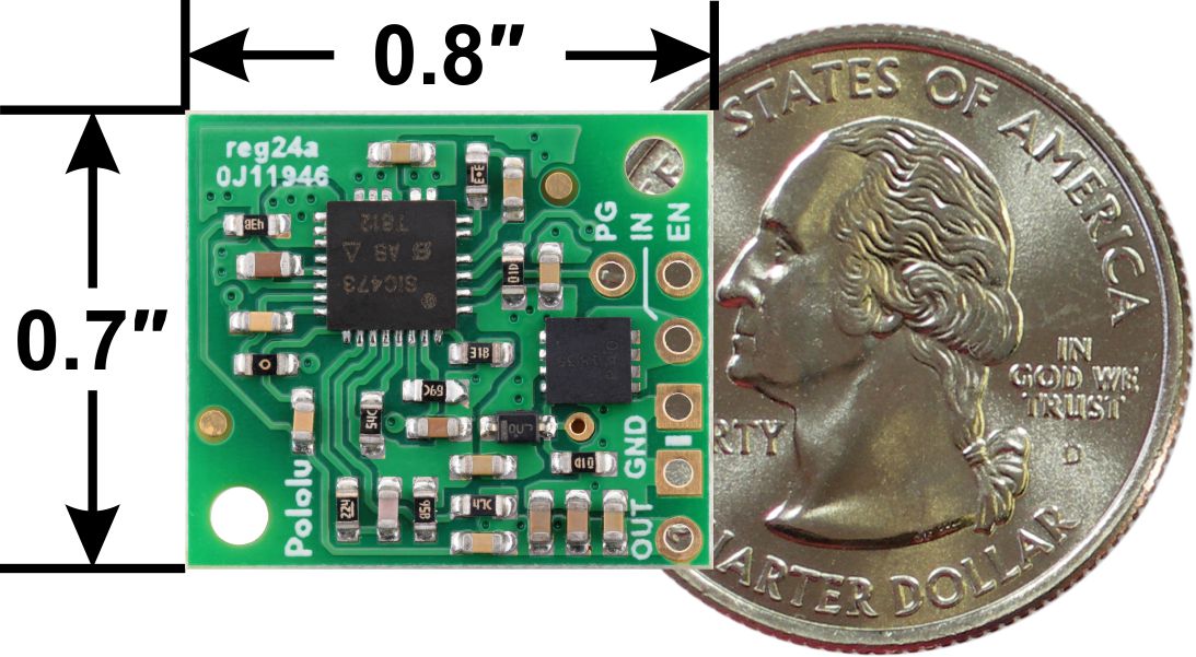
This small synchronous switching step-down (or buck) regulator takes an input voltage of up to 50 V and efficiently reduces it to 12 V. The board measures only 0.7″ × 0.8″ yet delivers typical maximum continuous output currents between 2 A and 3.3 A, depending on the input voltage, which makes it well suited for powering moderate loads like sensors or small motors. An optional enable input can be used to put the regulator in a low-power state with a current draw of 10 µA to 20 µA per volt on VIN. The regulator also features reverse voltage protection and a power-good output that indicates when the regulator cannot adequately maintain the output voltage. The pins have a 0.1″ spacing, making this board compatible with standard solderless breadboards and perfboards.
The D36V28Fx family of buck (step-down) voltage regulators generates lower output voltages from input voltages as high as 50 V. They are switching regulators (also called switched-mode power supplies (SMPS) or DC-to-DC converters), which makes them much more efficient than linear voltage regulators, especially when the difference between the input and output voltage is large. These regulators can typically support continuous output currents between 2 A and 4 A, depending on the input voltage and output voltage (see the Maximum continuous output current section below). In general, the available output current is a little higher for the lower-voltage versions than it is for the higher-voltage versions, and it decreases as the input voltage increases.
This family includes six versions with fixed output voltages ranging from 3.3 V to 12 V:
- D36V28F3: Fixed 3.3V output
- D36V28F5: Fixed 5V output
- D36V28F6: Fixed 6V output
- D36V28F7: Fixed 7.5V output
- D36V28F9: Fixed 9V output
- D36V28F12: Fixed 12V output
The regulators have reverse voltage protection up to 40 V, output undervoltage and overvoltage protection, over-current protection, and short-circuit protection. A thermal shutdown feature also helps prevent damage from overheating and a soft-start feature limits the inrush current and gradually ramps the output voltage on startup.
Features
- Input voltage: 12.9 V to 50 V (minimum input subject to dropout voltage considerations; see the dropout voltage section for details)
- Output voltage: 12 V with 4% accuracy
- Typical maximum continuous output current: 2 A to 3.3 A (see the maximum continuous output current graph below)
- Typical efficiency of 90% to 95%, depending on input voltage, output voltage, and load (see the efficiency graph below)
- Switching frequency: ~500 kHz under heavy loads
- Power-save mode with ultrasonic operation that increases light load efficiency by reducing switching frequency, but keeps it above the audible range (20 kHz)
- 1 mA to 3 mA typical no-load quiescent current (see the quiescent current graph below)
- Enable input for disconnecting the load and putting the regulator into a low-power state that draws approximately 10 µA to 20 µA per volt on VIN
- “Power good” output indicates when the regulator cannot adequately maintain the output voltage
- Output undervoltage and overvoltage protection
- Soft-start feature limits inrush current and gradually ramps output voltage
- Integrated reverse-voltage protection up to 40 V, over-current and short-circuit protection, over-temperature shutoff
- Compact size: 0.7″ × 0.8″ × 0.345″ (17.8 mm × 20.3 mm × 8.8 mm)
- Two 0.086″ mounting holes for #2 or M2 screws
Connections:
This regulator has six connections: power good (PG), enable (EN), input voltage (VIN), output voltage (VOUT), and two ground (GND) connections.
The “power good” indicator, PG, is an open-drain output that goes low when the regulator’s output voltage either rises more than 20% above or falls more than 10% below the nominal voltage (with hysteresis). An external pull-up resistor is required to use this pin.
The EN pin is pulled-up to reverse-protected VIN by a 100 kΩ resistor, which enables the regulator’s output by default. The EN pin can be driven low (under 0.4 V) to put the board into a low-power state. The quiescent current draw in this sleep mode is dominated by the current in the pull-up resistor from EN to VIN and by the reverse-voltage protection circuit, which altogether will draw between 10 µA and 20 µA per volt on VIN when EN is held low. If you do not need this feature, you can leave the EN pin disconnected.
The input voltage, VIN, powers the regulator. Voltages up to 50 V can be applied to VIN. Generally, the effective lower limit of VIN is VOUT plus the regulator’s dropout voltage, which varies approximately linearly with the load (see below for graphs of the dropout voltage as a function of the load).
VOUT is the regulated output voltage.
The six connections are arranged on 0.1″ grid for compatibility with solderless breadboards, connectors, and other prototyping arrangements that use a 0.1″ grid. The PG connection is the only one not located along the edge of the board. A 6×1 straight male header strip and a 5×1 right-angle male header strip are is included with the regulator; one pin of the straight header can optionally be broken off and soldered into PG.
Dimensions
| Size: | 0.7″ × 0.8″ × 0.345″1 |
|---|---|
| Weight: | 3.3 g1 |
General specifications
| Minimum operating voltage: | 12.9 V2 |
|---|---|
| Maximum operating voltage: | 50 V |
| Continuous output current: | 2.4 A3 |
| Output voltage: | 12 V |
| Reverse voltage protection?: | Y4 |
| Maximum quiescent current: | 3 mA5 |
| Output type: | fixed 12V |
Identifying markings
| PCB dev codes: | reg24a |
|---|---|
| Other PCB markings: | 0J11946 |
Notes:
- 1
- Without included optional headers.
- 2
- Subject to dropout voltage considerations. See the dropout voltage graph under the description tab for more information.
- 3
- Typical continuous output current at 36 V in. Actual achievable continuous output current is a function of input voltage and is limited by thermal dissipation. See the output current graph under the description tab for more information.
- 4
- To -40 V. Connecting supplies over 40 V in reverse can damage the device.
- 5
- While enabled with no load. Can be reduced to under 1 mA using the enable pin.
File downloads
- Dimension diagram of the Step-Down Voltage Regulator D36V28Fx (306k pdf)
- 3D model of the Step-Down Voltage Regulator D36V28Fx (5MB step)
- Drill guide for the Step-Down Voltage Regulator D36V28Fx (31k dxf)
- This DXF drawing shows the locations of all of the board’s holes.
ביקורת : הערה ללא תרגום מ HTML!
דירוג רע טוב
הכנס את הקוד התיבה

לחץ להגדיל

לחץ להגדיל

לחץ להגדיל

לחץ להגדיל

לחץ להגדיל

לחץ להגדיל

לחץ להגדיל
